Dum break tutorial
1. Analysis overview
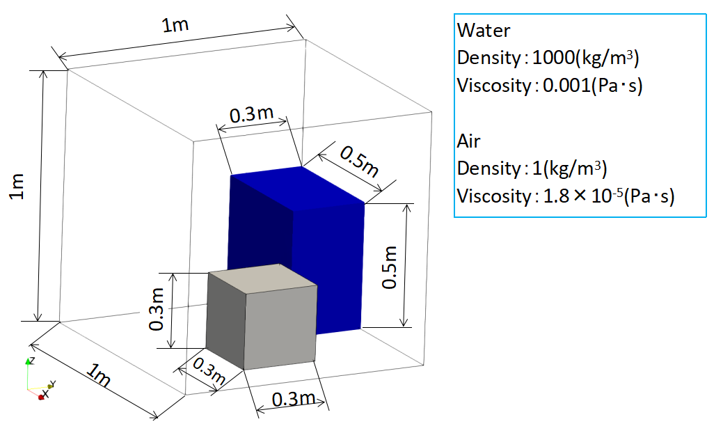
A box with an open ceiling of 1m on a side has a block of 0.3m per side fixed inside.
0.5m×0.3m×0.5m water is dammed and released at t=0[s] to observe the behavior of the water.
Approximate values are used for physical properties of water and air.
Use the density of water to 1000 (kg/m3) and the viscosity coefficient to 0.001 (Pa・s).
Use the air density to 1 (kg/m3) and the viscosity coefficient to 1.8×10⁻⁵ (Pa・s).
Please download the geometry data used for this simulation from here.
* Points are required for this simulation, so please receive them in advance from Settings → Receive points.
2. Geometry
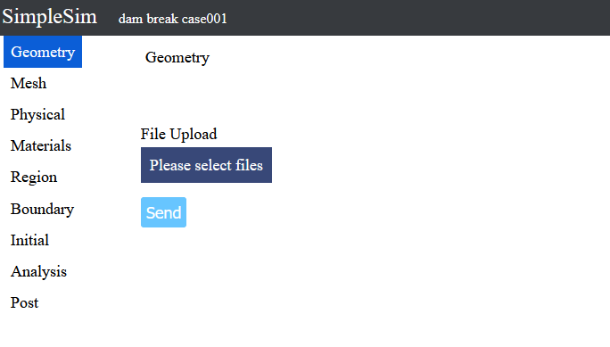
When you access the dam break case, you will see a page like this.
Upload geometries file for analysis on this page
When the file than can be downloaded in 1. Analysis overwiew is decompressed, it contains dambreak.stl, so it will be used this time.
Press the Please select files button, select dambreak.stl and press the Open button.
dambreak.stl will be displayed under the Please select files button, so press the Send button to upload file.
When the upload is completed, the 3D model will be displayed on the right side.
The 3D model can be rotated by dragging the left button.
The 3D model can be zoomed in and out by dragging the center button or rotating the center wheel.
The 3D model can be translated by dragging the right button.
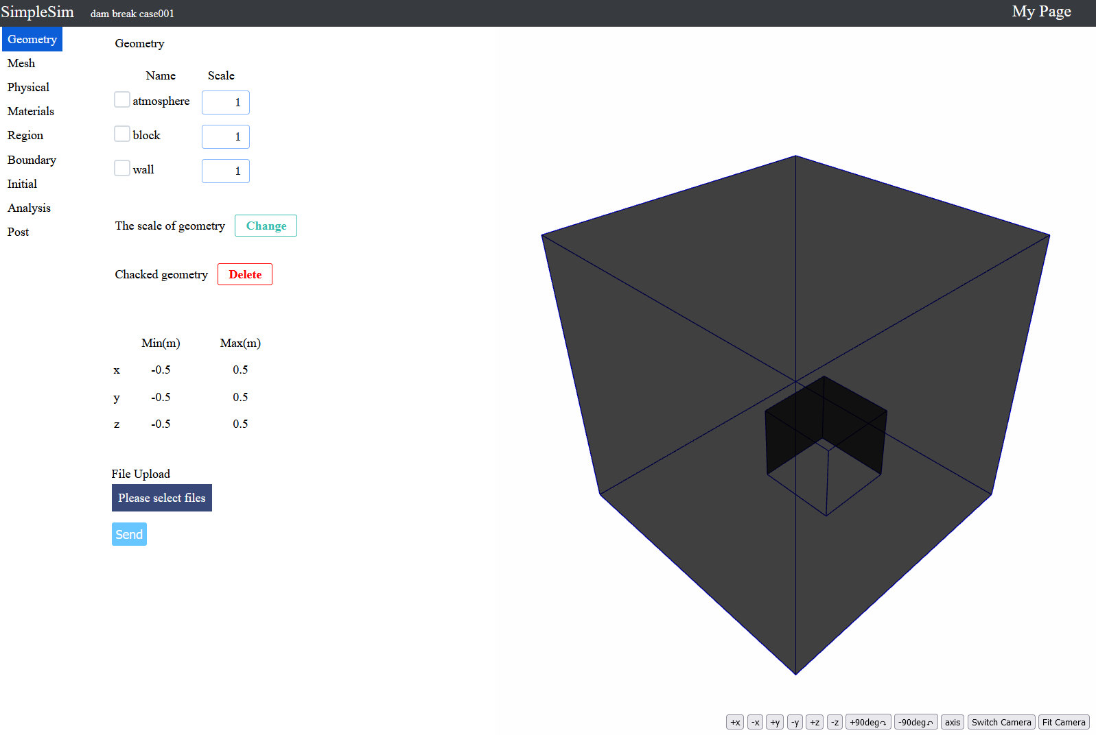
When the upload is completed, the 3D model will be displayed on the right side.
The 3D model can be rotated by dragging the left button.
The 3D model can be zoomed in and out by dragging the center button or rotating the center wheel.
The 3D model can be translated by dragging the right button.
3. Mesh
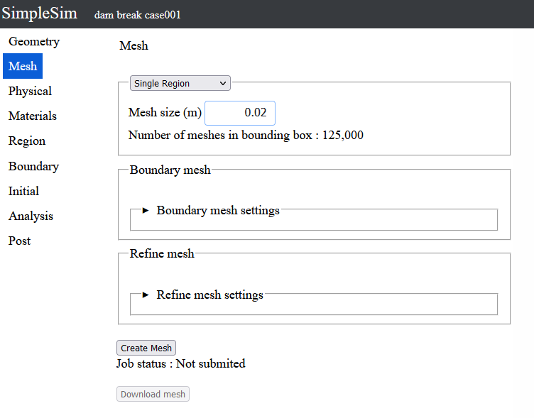
To click the mesh button on the left make the mesh setting page be moved to.
Enter 0.02 for the mesh size.
Now that the mesh inputs iscomplete, press the Create Mesh button.
Press Yes on the confirmation window to submit the job.
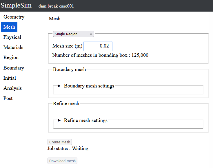
The job has been submited and the job status is waiting.
When the turn of the job comes, the mesh creation will start.
You can wait for the mesh creation to be completed, but you can proceed with the analysis settings without waiting for it to be completed, so proceed with the analysis settings.
*If you wait until it is completed, you can download the mesh.
4. Physical models
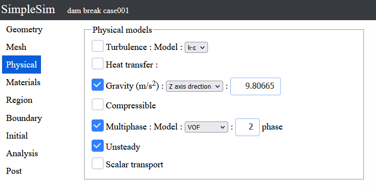
To click the Physical button on the left, the Physical models setting page can be moved to.
On this page, you can set on/off for heat transfer, gravity, etc.
Turn on gravity, multiphase flow, and unsteady.
Change the direction of gravity to the Z axis direction.
5. Materials
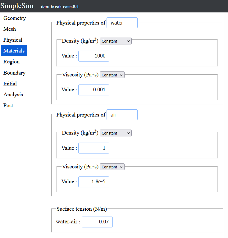
To click the Material button on the left, the Physical properties setting page can be moved to.
Rename phase1 to water.
Enter 1000 for density.
Enter 0.001 for the viscosity.
Rename phase2 to air.
Enter 1 for density.
Enter 1.8e-5 for the viscosity.
The default value of 0.07 is used for surface tension, so there is no need to change it.
6. Regions
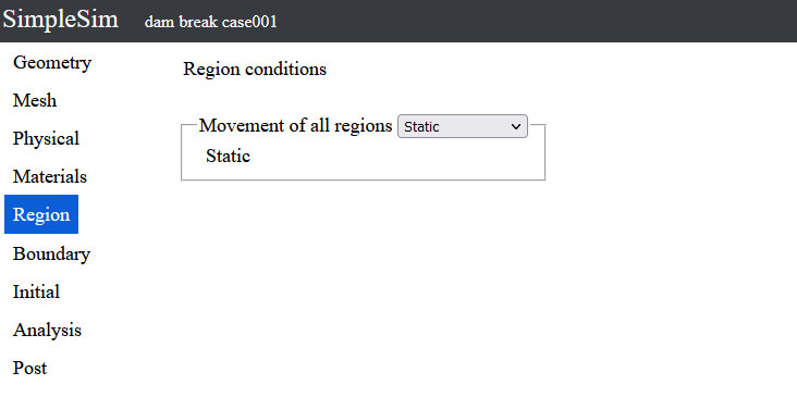
To click the Region button on the left, the Region conditions page can be moved to.
Here you can set the movement of all regions.
This time the analysis domain is static, so leave the select box value "static".
7. Boundary conditions
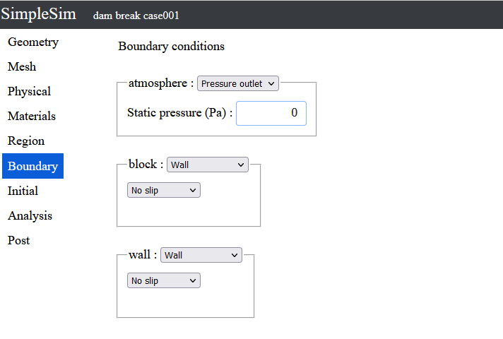
To click the Boundary button on the left, the boundary conditions page can be moved to.
Select the pressure outlet from the select box to the right of the atmosphere.
The pressure outlet is a boundary that flows freely by specifying a pressure on the boundary.
A default value of "0" is used for the pressure
There is no need to change the default values of wall for block and wall.
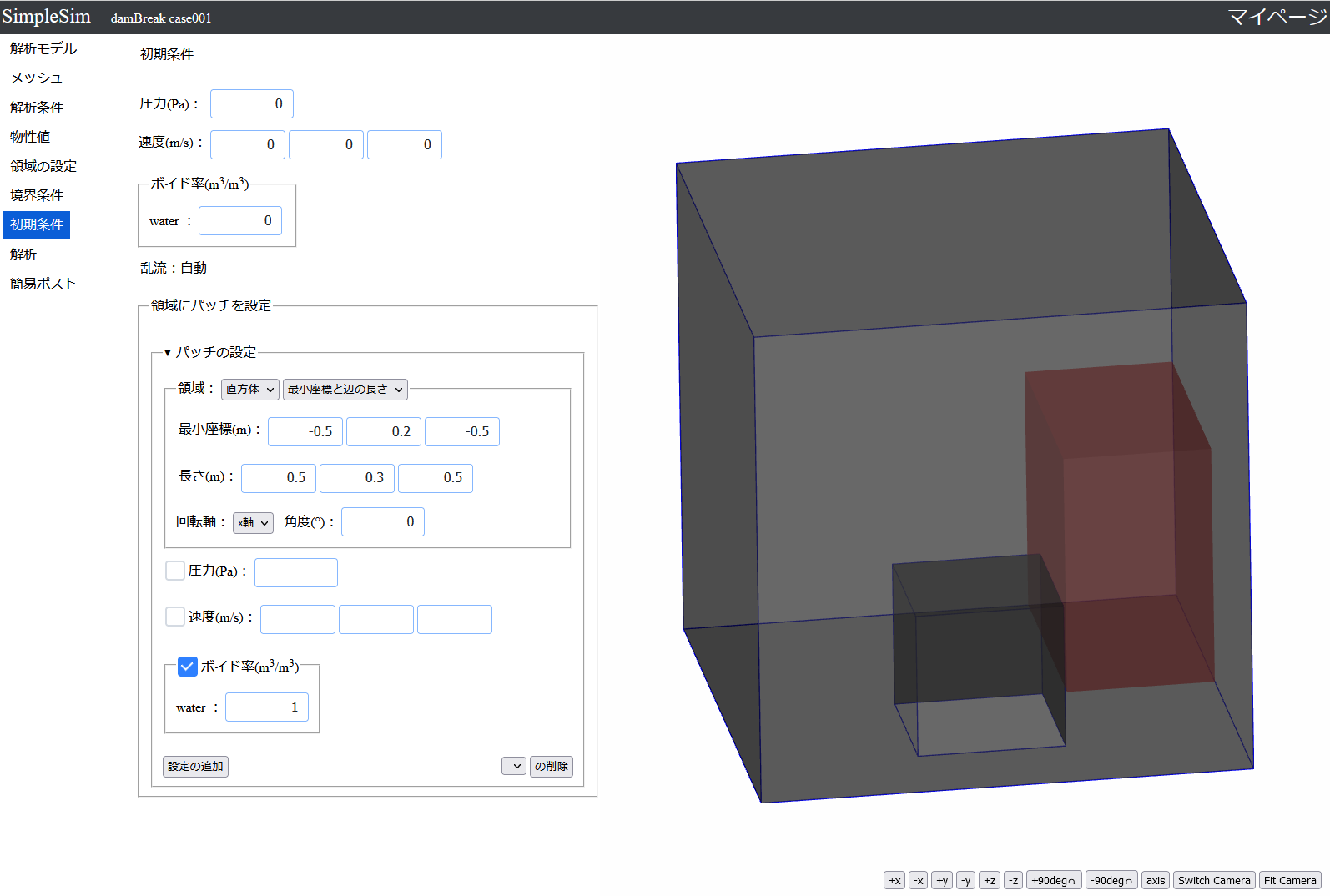
8. Initial conditions
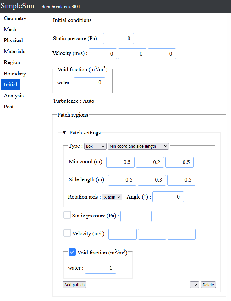
To click the Initial button on the left, the initial conditions page can be moved to.
All initial conditions use default values and set the entire region to zero velocity air.
The water settings are set by patch regions.
Click on the patch settings to open it and configure it.
The type is box, and the select box next to it is the minimum coordinate and side length.
Enter (-0.5 0.2 -0.5) for the minimum coordinates.
Enter (0.5 0.3 0.5) for the length.
Check the void fraction checkbox.
Enter a value of 1 for water.
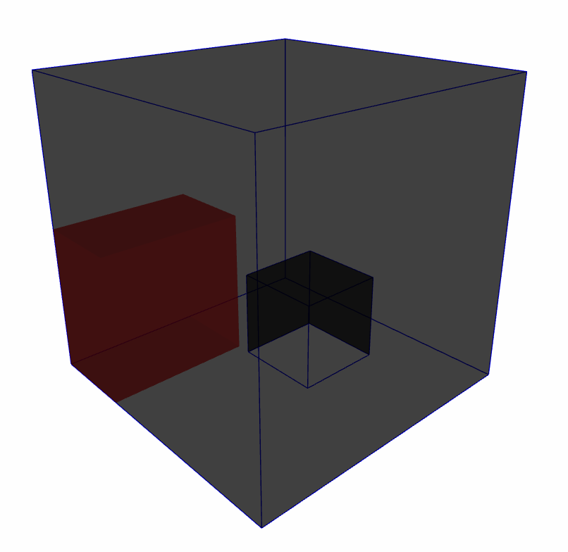
After entering the minimum coordinates and side length, the patch region will be displayed in red in the 3D model display area on the right side.
Confirm that there are no mistakes and press the Add Patch button.
9. Analysis
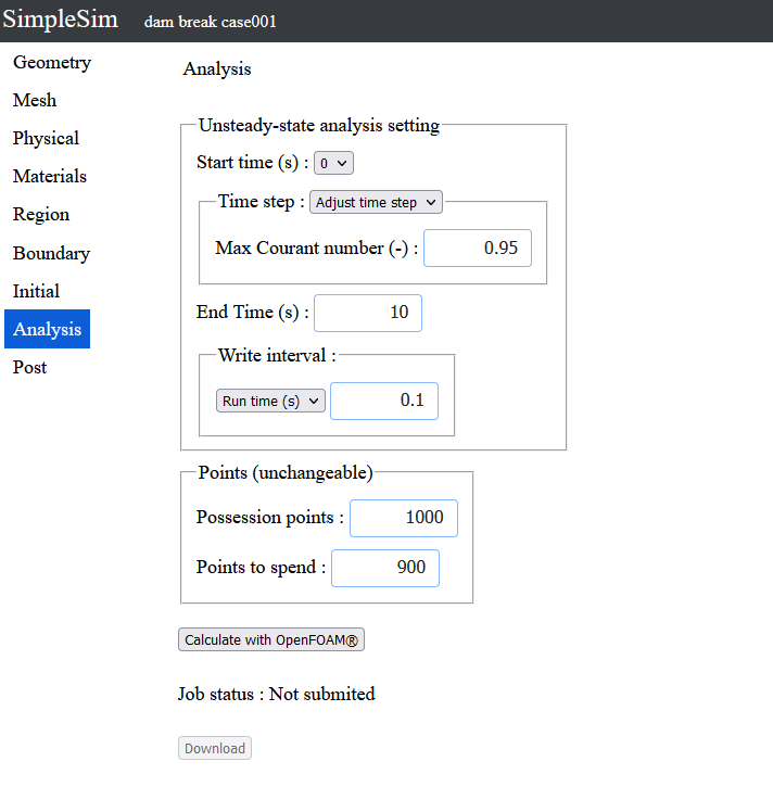
To click the Analysis button on the left, the analysis page can be moved to.
Enter 10 for the end time (s).
Enter 0.1 for the run time (s) of the write interval.
Click the "Calculate with OpenFOAM" button to analyze.
Press Yes on the confirmation window to submit the job.
10. Post processnig
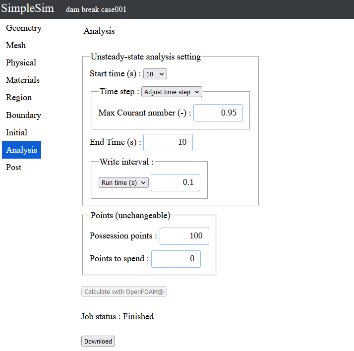
After the calculation is completed, the analysis data can be downloaded.
Click the "Download" button to download the data.
Unzip the downloaded file and perform post processing using ParaView, etc.
The behavior of water will be like the movie on the right.
To the Tutorial List
Update January 05, 2023