Mixing elbow tutorial
1. Analysis overview
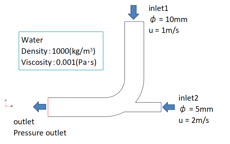
This is an analysis of the internal flow of a shape in which eblow with a thin pipe.
Water flows into the mixing elbow at 1 m/s from inlet1, flows into the mixing elbow at 2 m/s from inlet2, and flows out the outlet.
Approximate values are used for physical properties of water.
Set the density of the water to 1000 (kg/m3) and the viscosity of the water to 0.001 (Pa・s).
Please download the data used for this analysis here.
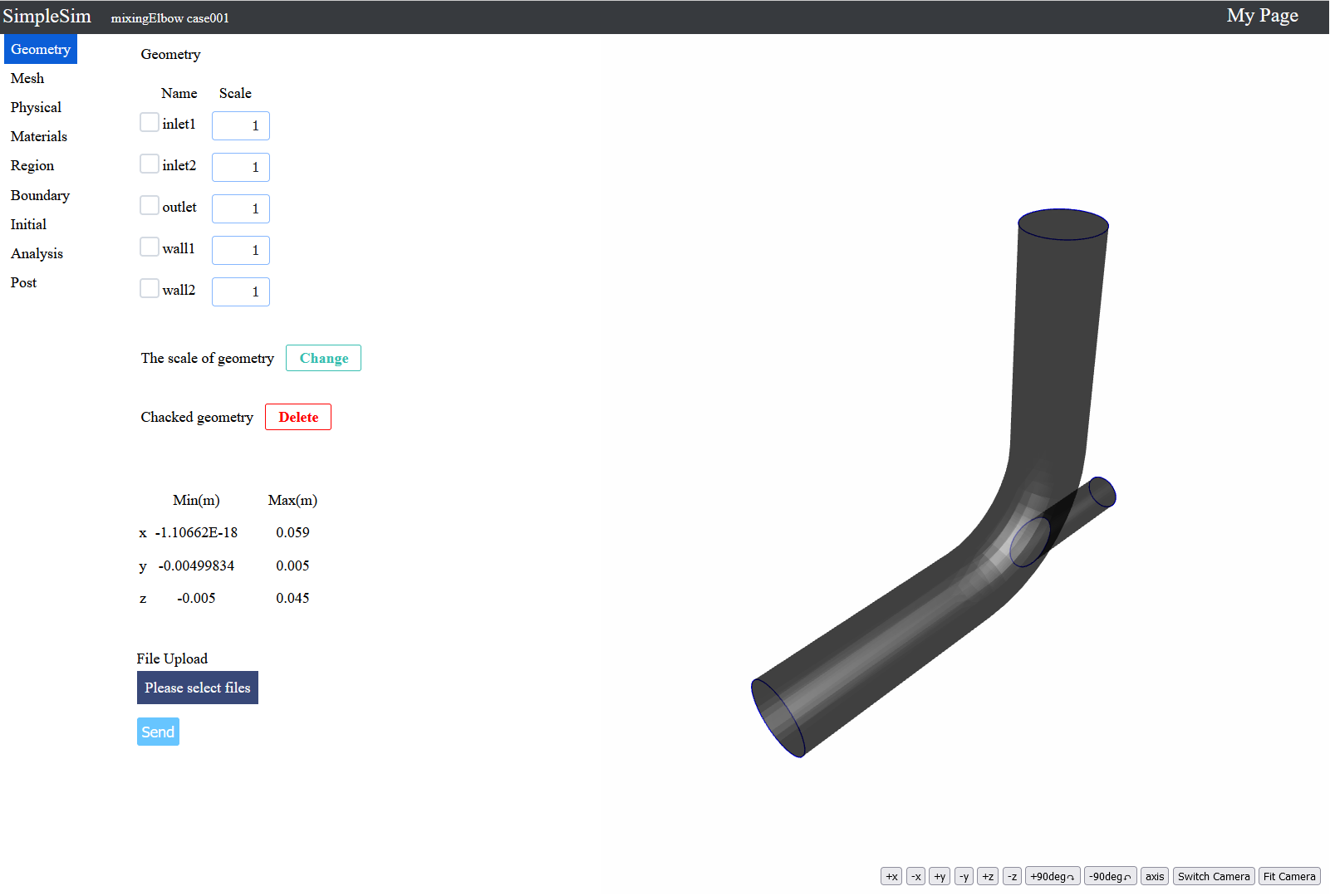
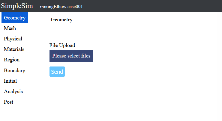
2. Geometry
When you access the case file, you will see this screen.
Upload geometries for analysis on this screen.
When the file than can be downloaded in "1. Analysis overwiew" is decompressed, it contains "elbow.stl", so it will be used this time.
Press the "Please select files" button, select "elbow.stl" and press the Open button.
"elbow.stl" will be displayed under the "Please select files" button, so press the "Send" button to upload file.
When the upload is completed, the 3D model will be displayed on the right side.
The 3D model can be rotated by dragging the left button.
The 3D model can be zoomed in and out by dragging the center button or rotating the center wheel.
The 3D model can be translated by dragging the right button.
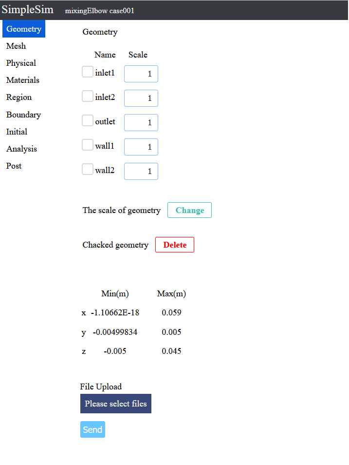
The geometries name and scale are displayed at the top of the center.
The maximum and minimum coordinates of the entire geometries are displayed at the bottom center.
You can change the scale of the geometry by changing the scale to the right of the geometry name and press the Cnage geometry Scale button.
You can delete geometries by checking the checkbox to the left of the geometry name and pressing the Delete button for the checked geometries.
3. Mesh
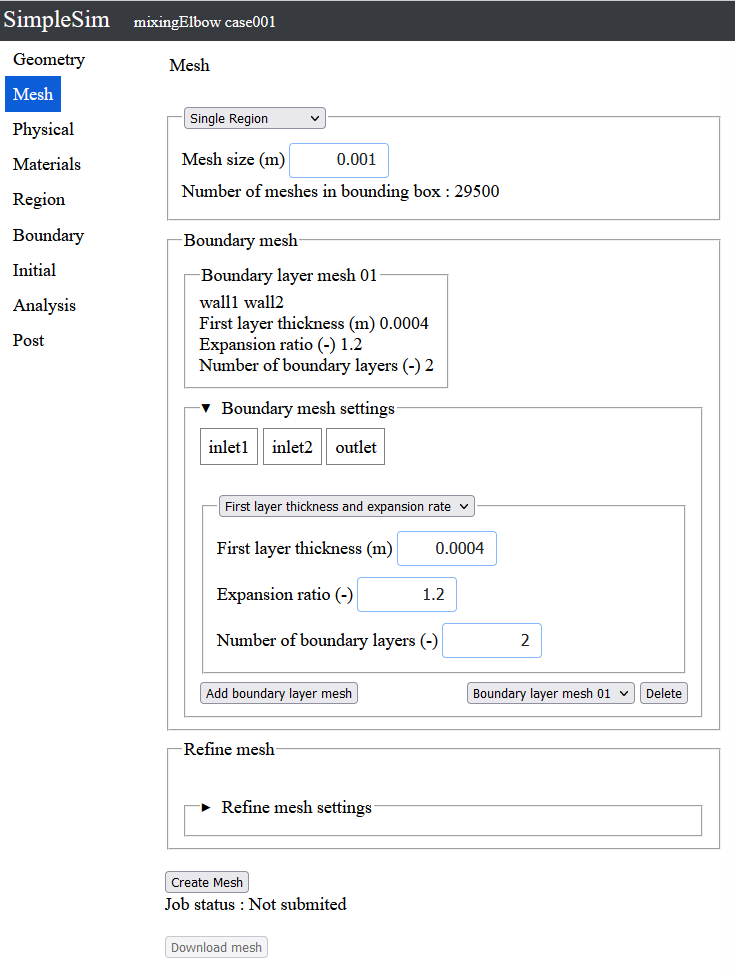
To click the mesh button on the left make the mesh setting screen be moved to.
Enter "0.001" for the mesh size.
Next, set the boundary layer mesh.
Click "▶Boundary layer mesh settings" to display the boundary layer mesh settings.
Click "wall1" and "wall2" to make them selected.
Enter "0.0004" for the first layer thickness.
Enter "1.2" for expansion ratio.
Enter "2" for number of boundary layers.
After entering the information, press the add boudary layer mesh button.
Boundary layer mesh 01 has been added above the boudary layer settings.
Now that the mesh inputs iscomplete, press the Create Mesh button.
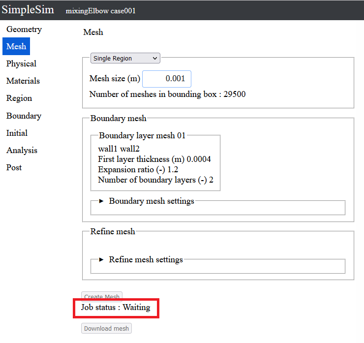
The job has been submited and the job status is waiting.
When the turn of the job comes, the mesh creation will start.
You can wait for the mesh creation to be completed, but you can proceed with the analysis settings without waiting for it to be completed, so proceed with the analysis settings.
*If you wait until it is completed, you can download the mesh.
4. Physical models
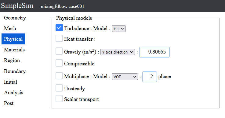
To click the Physical button on the left, the Physical models setting screen can be moved to.
On this screen, you can set on/off for heat transfer, gravity, etc.
Since this analysis is turbulent, turn on the turbulence checkbox.
5. Materials
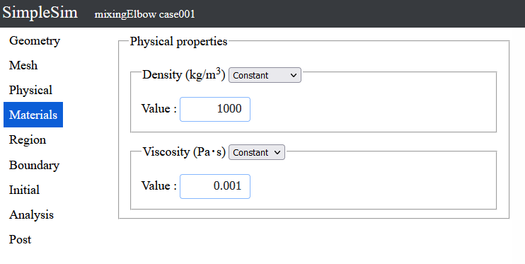
To click the Material button on the left, the Physical properties setting screen can be moved to.
Enter "1000" for density.
Enter "0.001" for viscosity.
6. Regions
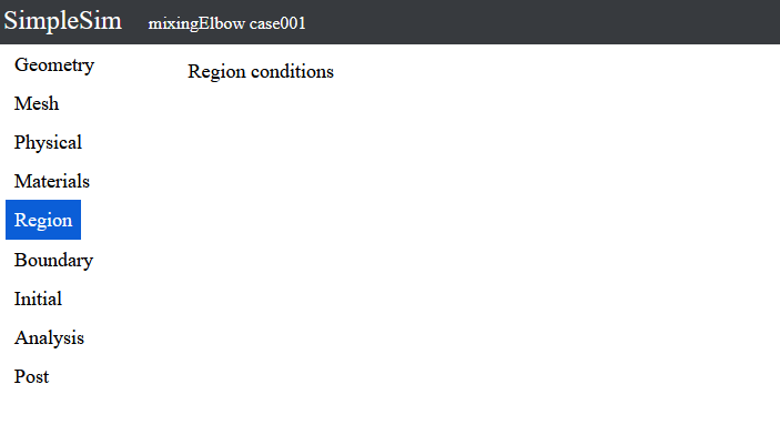
To click the Region button on the left, the Region conditions screen can be moved to.
No items can be changed in the Region conditions at this time.
7. Boundary conditions
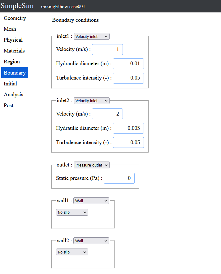
To click the Boundary button on the left, the boundary conditions screen can be moved to.
Select Velocity inlet from the select box to the right of inlet1.
Velocity inlet is a boundary with a constant velocity inflow normal to the boundary.
Enter "1" for velocity.
Enter "0.01" for hydraulic diameter.
Use the default value of 0.05 for the turbulence intensity
Select Velocity inlet from the select box to the right of inlet2.
Enter "2" for velocity.
Enter "0.005" for hydraulic diameter.
Use the default value of 0.05 for the turbulence intensity
Select pressure outlet from the select box to the right of outlet.
Pressure outlet is a boundary that flows freely by specifying a pressure on the boundary.
Use the default value of 0 for the pressure
No need to change the settings of wall1 and wall2 as the default value of wall.
8. Initial conditions
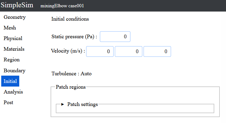
To click the Initial button on the left, the initial conditions screen can be moved to.
Use all default values.
9. Analysis
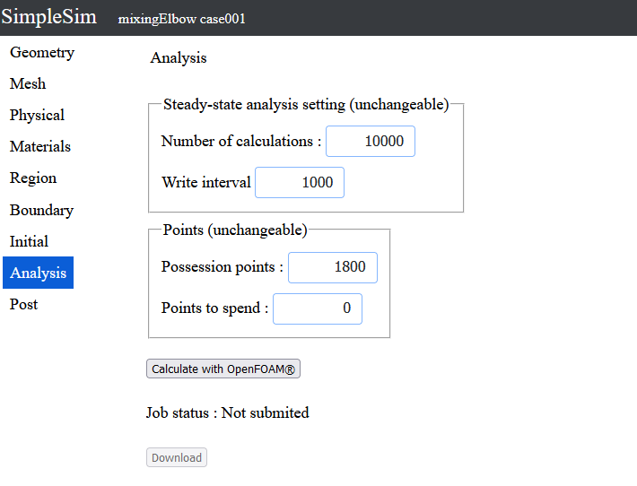
To click the Analysis button on the left, the analysis screen can be moved to.
Currently, the number of calculations connot be changed for steady-state analysis.
Calculate 10000 times without convergence judgement.
Click the "Calculate with Openfoam" button to analyze.
10. Post processnig
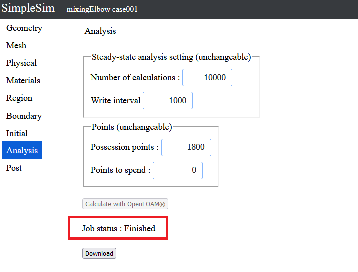
After the calculation is completed, the analysis data can be downloaded.
Click the "Download" button to download the data.
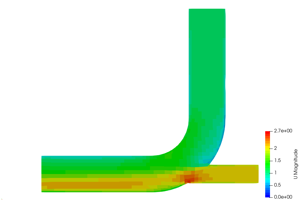
Unzip the downloaded file and perform post processing using ParaView, etc.
The velocity contour is shown on the right.
To the Tutorial List
Update Novenber 29, 2022